Oscilloscope Videos:
Controls Photo:
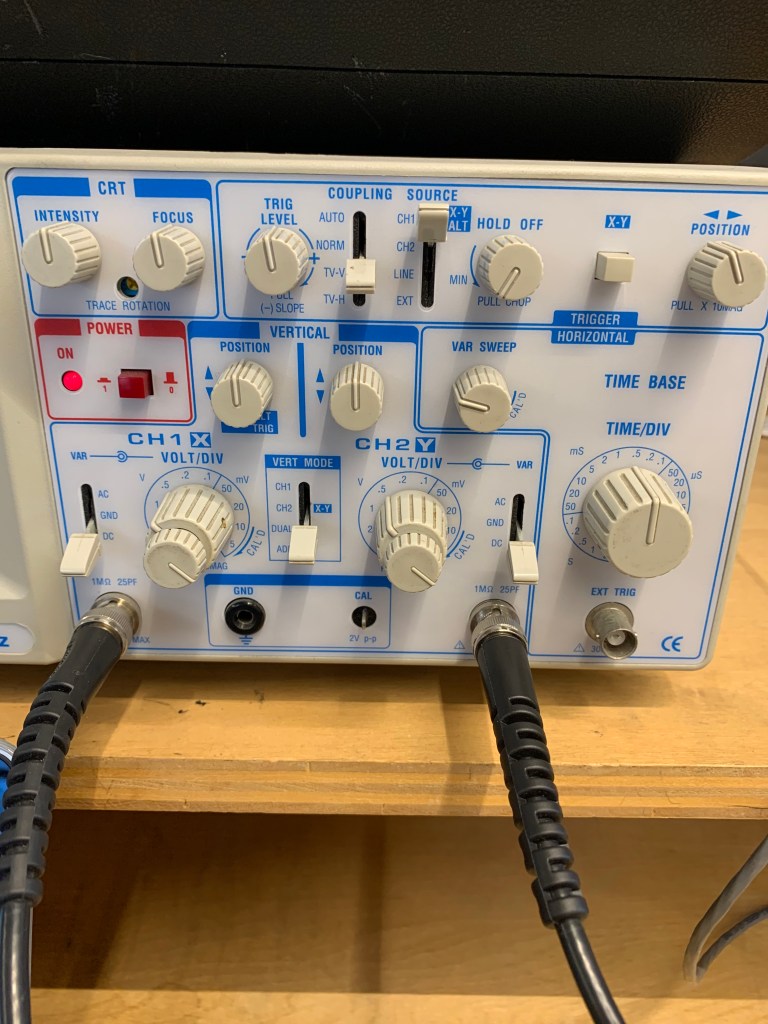
Controls of the Oscilloscope Explanation:
Power: The power button, which varies in location on each oscilloscope but is generally fairly obvious, turns the oscilloscope on and off.
Input Mode: The input mode controls what type of signal is visible on the screen of the oscilloscope. A ground signal will show just a straight line, since it is set to show zero (ground level), and DC will show the actual signal, since it is set to project the signal. Always set the oscilloscope to DC when attempting to see the signal, as AC will show something confusing in our situation.
View Mode: The view mode shows which signal is present on the screen of the oscilloscope. The CH.1 mode will show the signal from channel 1, the CH.2 mode will show the signal from channel 2, the DUAL mode will show both of them at the same time, and the ADD mode will show the two signals summed together.
Vertical Position Knobs: The vertical position knobs move each signal from channel 1 and channel 2 up and down on the grid. Set it to 12 o’clock in our case to properly see the signal. Other knobs, like the Intensity, Focus and Horizontal Position knobs, can also help to make the signal(s) appear clearly on the screen.
Volts Per Div Knobs: The small knob on the volts per div control should always be turned all the way to the right until it clicks. The larger knob on the volts per div control controls the vertical display and is measured in volts per division. Each division represents one of the squares made by the vertical and horizontal lines. Adjusting this will control how “tall” the wave appears on the screen. However, it is important to note that we are only adjusting how the wave appears on the screen, not altering the amplitude or any other property of the signal in changing the appearance. In our case, setting it to 0.5V will provide the clearest picture.
Time Per Div Knobs: The time per div knobs control horizontal display, and is measured in time per division. Adjusting this will control how “long” or “short” the wave appears by zooming in and out on the wave, by adjusting how much time each division shows. It is important to note that we are only adjusting how zoomed in the signal appears, not altering the actual wavelength or frequency of the signal. We can use this knob to alter how many complete waves the display will show. In our case, we want to see 2-4 full waves, and setting it to around 0.5mS/div will help us achieve this.
Trigger Controls:
Most simply, the trigger controls just tell the oscilloscope at which point in the signal to begin drawing the waveform based on a certain voltage. We can think of them as controls as providing the voltage a selected signal must meet in order for the oscilloscope to begin drawing the signal(s) from the channel(s).
Trigger Level: The trigger level sets the voltage level at which the oscilloscope will begin drawing. In our case, keeping it right at 12 o’clock will give us a clear view of our signal.
Trigger Source: The trigger source determines which signal must be at the certain voltage set by the trigger level in order for the oscilloscope to begin drawing. In our case, we will set this to Channel 1. It is important to note that just because we are setting this to Channel 1, we will still be able to view the signals from both Channel 1 and Channel 2. The trigger source is completely independent from View Mode; trigger source is just selecting the signal that must meet a certain voltage in order for the oscilloscope to begin drawing the signal(s).
Trigger Mode: The trigger mode determines when the oscilloscope will draw the signal, based on different requirements that are determined by the given mode setting. In our case, we can set the trigger mode to either AUTO or TV-V
Trigger Position: The trigger position knob essentially holds the wave in place, by properly aligning it horizontally and subsequently timing it correctly. In our case, set the knob right in the middle to align it for observation.
Volts Per Div. vs. Time Per Div.
The oscilloscope seeks to show the difference in voltage overtime. Time is on the X-axis, and voltage is on the Y-axis. “Volts per div” controls the vertical display, in that adjusting it will change the amount of volts visible in each division on the oscilloscope, and subsequently change how the wave is presented vertically. Lowering the number of volts per division will make the wave appear “taller,” in that not as many volts can fit into each division. Conversely, raising the number of volts per division will make the wave appear “shorter” (in terms of the vertical) or smaller, in that each division can hold more volts. “Time per div” controls the horizontal display, and adjusting it will change how much time is in each division, resulting in alterations in how the wave appears horizontally. Increasing the time per div will allow the user to see more cycles of the waveform, as they are allowing each division to show how the wave moves over a greater time per division. Alternatively, decreasing the time per div will allow the user to see less cycles of the waveform, as they are allowing each division to show how the wave moves over less time per division. Adjusting these controls will allow the user to find the clearest, most sensical way for them to view the wave. However, it is important to note that we are only adjusting the visual parameters of the signal, and we are not changing characteristics of the actual waveform.
Trigger Controls Explanation
The “trigger” controls in the most basic sense all contribute to telling the oscilloscope at which point in the signal to begin drawing the waveform by setting a certain voltage that a certain signal must meet in order for the oscilloscope to draw. This primarily involves four different controls: trigger level, trigger source, trigger mode, and trigger position. Trigger level controls the level of voltage required for the selected signal to meet to allow the oscilloscope to draw. Setting it right in the middle is a good idea for our situation. Trigger source determines which signal must meet this voltage. In our case, we want this to be the input or channel one signal, so we would set the trigger source to CH.1. The trigger mode decides when the oscilloscope will draw the waveform, based on different requirements determined by each mode. For this lab, it is most appropriate to use AUTO or TV-V mode. Finally, the trigger position allows the user to hold the wave in the proper place. In our situation, setting the knob in the middle will allow us to view it properly.
Connecting the Breadboard to the Oscilloscope
To connect the breadboard to the oscilloscope, first, insert two black probes on the ground rail of the breadboard. It is important that these are on the ground rail, as there is no power running through the circuit! For the first channel, clip the black clip to one of probes, and clip the red clip to the green wire on the outside of the potentiometer that is directly connected to the resistor. For the second channel, clip the black clip to the remaining probe, and clip the red clip to the other green wire that is connected to the middle of the potentiometer.
Potentiometers with Input and Output
As I turn the potentiometer, I am increasing the level on the output signal by gradually decreasing the amount of resistance on the output signal. When it is turned all the way to the left, the resistance is maximized and the amplitude is minimized, and subsequently it just appears as a straight line on the oscilloscope. As I turn it to the right, I am decreasing this resistance, and as a result, and the signal’s amplitude increases on the oscilloscope. When it is turned all the way to the right, there is no resistance, and the signal can be seen (and heard if plugged into a speaker) at its full amplitude (or volume). In this case, the potentiometer is really just a volume knob. The minimum amplitude of the output wave as a percentage of the input wave is 0% when there is maximum resistance and the potentiometer is turned all the way to the left, and the maximum amplitude of the output wave as a percentage of the input wave is 100% when there is no resistance and the potentiometer is turned all the way to the right. The maximum can only be 100% because it would be impossible for the output to be at a greater volume or amplitude than the input, as there is no amplifier.
Troubleshooting Notes
Made a few mistakes this week. Check them out here!
Additional Resources
I found some of the controls a little confusing this week, especially the trigger controls, so I used some additional resources to figure out the answers to these questions.
https://core-electronics.com.au/tutorials/oscilloscope-triggers-what-how.html
https://learn.sparkfun.com/tutorials/how-to-use-an-oscilloscope/all
