So, how do breadboards work?
Breadboards are a basic foundation for building different electrical circuits. Generally, they are made of plastic and maintain many different tiny, evenly-spaced holes, containing pieces of metal that bind onto various wires, and allow electricity to flow through them. The bread board is divided into a few different sections. Between the red line and blue line, in the center of the breadboard, the middle section columns are labeled A-J, and on our breadboard, the rows are labeled from 1-64. There is a divider in this middle section that is helpful in seeing where the electrical connections begin and end. All of that holes are in the same row from columns A-E are connected, and all of the holes that are in the same row from columns F-J are connected. It is important to note that the holes between these two sections are not connected. For example, hole E5 and F5 are not connected, although they share the same row.
On the outside of the breadboard, there are two sections with holes that lie on rails. The red line is the power rail, which handles positive charge, and the blue line is the ground rail, which handles negative charge. The holes in the column closest to the red line are on the power rail, while the holes in the column closest to the blue line are on the ground rail. In order to connect a battery, for example, the positive red wire would be in a hole on the power rail, and the negative black wire would be in a hole on the ground rail. All of the holes in a particular column within one exterior section of the breadboard are connected. This means that all of the holes on the power rail on one of the outside sections of the breadboard are connected and all holes on the ground level on one of the outside sections of the breadboard are connected. It is also important to note that while the holes are connected by column in each section, the two exterior sections are not connected. The image below shows these connections on a smaller breadboard. After establishing how the connections work, it becomes far more simple to figure out how to effectively arrange the circuit.

Circuit:
Video of Circuit:
Schematic
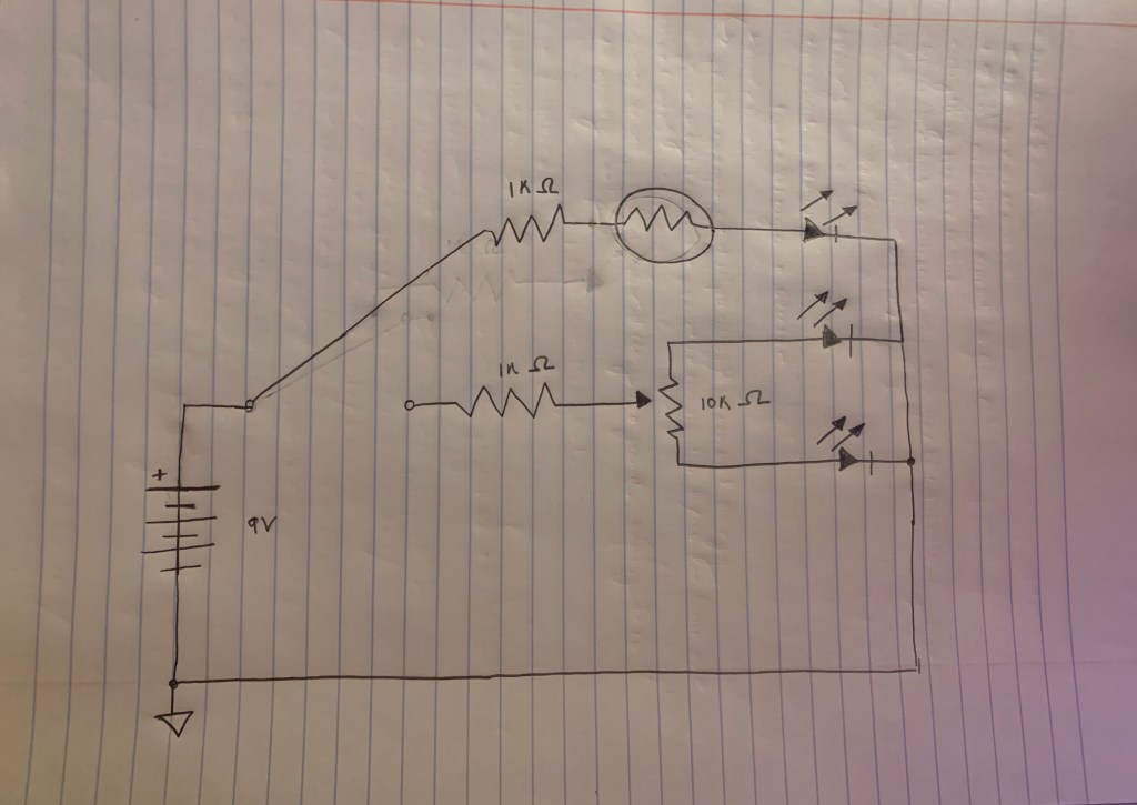
Bonus! (I tried…)
For my bonus circuit, I decided to remove one of the LED’s from the first potentiometer in the initial circuit, and connect it to another potentiometer that is not controlled by the switch, so that it would always be on no matter the setting on the switch. However, while I got the second potentiometer to work, the red LED blew out, so I couldn’t really get the full of effect of toggling between the two settings on the switch.
How do multimeters work?
Multimeters are utilized to measure the precise voltages of circuits to ensure that they are working properly. For example, in order to properly measure the voltage of a standard 9V battery, the positive test lead (red) on the positive side of the battery and the negative test lead (black) on the negative side of the battery. Plus and minus symbols indicate which side of the battery is positive or negative, where the plus is positive and the minus symbol is negative. Additionally, the smaller, more rounded connection at the top of the battery is the positive, while the larger, hexagonally shaped connection is the negative side. After placing the appropriate leads in the proper spaces, the multimeter will measure the difference between the positively-charged side and the negatively-charged side. Since it is a 9V battery, if it is new, it should measure to be 9V, however, 9V is not a perfectly accurate measurement of this voltage, and the multimeter will often measure it to be more than 9V. Voltage itself is the difference in electrical charge between two points, or how strongly the extra electrons on one side of the battery tend to pull themselves to the other side. So, in the case of a 9V battery, the difference of charge between the two sides is said to be roughly 9V.
Because batteries drain as they are used, checking them throughout the process of building a circuit can be useful in ensuring that the battery is still powering the circuit. The circuit will not work if the battery runs out of charge, and this can lead to major issues in the functioning of the circuit. Multimeters can also be used to check the voltage of the breadboard itself to check if power is flowing through it effectively. First, on either outer section of the bread board, insert two probes, one next to the blue ground rail, and one next to the red power rail. Then, place the multimeters test leads on the probes on the respective positive and negative rails. From here, we can check to see if power from the battery or other power source is running into the circuit. This is an easy initial place to start troubleshooting, rather than attempting to move around other more complicated aspects of the circuit when it may actually be a simple fix. In addition, multimeters can also measure resistance and current.
Week #1 Analog Circuit Troubleshooting Notes:
I made so many fun mistakes this week! Click here to see my notes!
Final Project Thoughts…
1.) Transistor and Diode Distortion Pedal – Tia Dizon
I found Tia’s project really cool and impressive in that she was able to completely replicate the functions of a Boss D-1 Distortion pedal. Her replication has the same knobs as the Boss pedal, including a gain knob, which controls the audio input and intensifies the distortion effect, the tone knob, which can be used to provide the same effects as a high pass or low pass filter, and a level knob, which controls how the signals are mixed together. I really enjoyed hearing her demonstrate the different effects, and thought that the math she used to create the circuit looked pretty overwhelming!
2.) Analog Synthesizer in a Laser Cut Enclosure – Amelia Murray
I really liked seeing how Amelia’s project worked and hearing the demonstration. She created a monophonic, 8-key triangle and square wave synthesizer. A switch on the back of synthesizer toggles back and forth between triangle waves and square waves, and a knob on the top of the synthesizer changes the pitches of the notes from the initial key of G. I also liked the enclosure that held the circuit, and thought it was really cool to see the process of how she was able to create it with a laser cutter on her blog post.
3.) Analog Synth with Touch Sensor Strip and Force Sensitive Resistor
– Justine Mastro
I think that Justine’s synthesizer project is really interesting and unique in the use of the touch sensor strip, which eliminates pauses that occur with pushing buttons to operate synthesizers. The top of the touch sensor produces higher pitches, while the bottom produces lower pitches. In addition, she added a force sensitive resistor, which allows the user to control how loud the synthesizer is through application of pressure. More pressure makes the note louder, while less pressure makes the note softer. Additionally, I also really liked the laser-cut enclosure which held the circuit.
