int blueLed = 7;                      // create variables for each of the components on the breadboard
int greenLed = 8;
int whiteLed = 9;
int yellowLed = 10;
int tempoPin = A13;
int potPin1 = A14;
int potPin2 = A15;
int potPin3 = A16;
int potPin4 = A17;
int octaveSwitch = 28;
int powerSwitch = 27;

int tempoVal = 0;                   //map variables
int lastTempoVal = 0;

int potVal1 = 0;
int lastPotVal1 = 0;
int potVal2 = 0;
int lastPotVal2 = 0;
int potVal3 = 0;
int lastPotVal3 = 0;
int potVal4 = 0;
int lastPotVal4 = 0;

int octave = 12;                    //octave switch variable


void setup() {
  pinMode(blueLed, OUTPUT);       //pinMode for LEDs and switches
  pinMode(greenLed, OUTPUT);
  pinMode(whiteLed, OUTPUT);
  pinMode(yellowLed, OUTPUT);
  pinMode(octaveSwitch, INPUT);
  pinMode(powerSwitch, INPUT);


}

void loop() {

  stepSequencer();                //stepSequencer and checkOctave
  checkOctave();

}


void stepSequencer() {                                           //stepSequencer function

  if (digitalRead(powerSwitch) == HIGH) {                       //powerSwitch must be turned on


    lastTempoVal = tempoVal;                                   // tempo map
    tempoVal = map(analogRead(tempoPin), 0, 1023, 100, 1000);


    lastPotVal1 = potVal1;                                    //first pitch
    potVal1 = map(analogRead(potPin1), 0, 1023, 60, 72);      //first pitch map
    digitalWrite(blueLed, HIGH);                              // the first LED and pitch turns on, the rest are off
    digitalWrite(greenLed, LOW);
    digitalWrite(whiteLed, LOW);
    digitalWrite(yellowLed, LOW);
    usbMIDI.sendNoteOn(potVal1 - octave, 127, 1);
    delay(tempoVal);                                          // the LED and pitch remains like this for a value determined by the pot
    usbMIDI.sendNoteOff(potVal1 - octave, 0, 1);              //note off

    lastPotVal2 = potVal2;                                    //second pitch
    potVal2 = map(analogRead(potPin2), 0, 1023, 60, 72);      //second pitch map
    digitalWrite(blueLed, LOW);                               // the second LED and pitch turns on, the rest are off
    digitalWrite(greenLed, HIGH);
    digitalWrite(whiteLed, LOW);
    digitalWrite(yellowLed, LOW);
    usbMIDI.sendNoteOn(potVal2 - octave, 127, 1);
    delay(tempoVal);                                         // the LED and pitch remains like this for a value determined by the pot
    usbMIDI.sendNoteOff(potVal2 - octave, 0, 1);             //note off

    lastPotVal3 = potVal3;                                  // third pitch
    potVal3 = map(analogRead(potPin3), 0, 1023, 60, 72);    //third pitch map
    digitalWrite(blueLed, LOW);                             // the third LED and pitch turns on, the rest are off
    digitalWrite(greenLed, LOW);
    digitalWrite(whiteLed, HIGH);
    digitalWrite(yellowLed, LOW);
    usbMIDI.sendNoteOn(potVal3 - octave, 127, 1);
    delay(tempoVal);                                      // the LED and pitch remains like this for a value determined by the pot
    usbMIDI.sendNoteOff(potVal3 - octave, 0, 1);          //note off

    lastPotVal4 = potVal4;                               // fourth pitch
    potVal4 = map(analogRead(potPin4), 0, 1023, 60, 72); //fourth pitch map
    digitalWrite(blueLed, LOW);                         // the fourth LED and pitch turns on, the rest are off
    digitalWrite(greenLed, LOW);
    digitalWrite(whiteLed, LOW);
    digitalWrite(yellowLed, HIGH);
    usbMIDI.sendNoteOn(potVal4 - octave, 127, 1);
    delay(tempoVal);                                  // the LED and pitch remains like this for a value determined by the pot
    usbMIDI.sendNoteOff(potVal4 - octave, 0, 1);      //note off
    digitalWrite(blueLed, LOW);                       //LEDs turn off
    digitalWrite(greenLed, LOW);
    digitalWrite(whiteLed, LOW);
    digitalWrite(yellowLed, LOW);
  }
}

void checkOctave() {                                  //checkOctave function
  if (digitalRead(octaveSwitch) == LOW) {             //if switch is off, octave is 0, won't add anything to the pitches
    octave = 0;
  }
  if (digitalRead(octaveSwitch) == HIGH) {            // if switch is on, octave is 12, will subtract an octave from the pitches
    octave = 12;
  }
}
While it may seem overly-simplified and even non-sensical at first glance, the button code utilized for MIDI keyboards, and all devices with keyboards is very easy to use, and very logical in its construction. In order to best understand the code, let’s walk through how it is written, and then observe it in action it from a very practical perspective: pressing a note and releasing it after a few short moments.
The first thing we need to do is establish some variables that we’ll use throughout the code. These variables are buttonState and lastButtonState. “buttonState” describes the status of the button, pushed or un-pushed, or in coding language, “HIGH” or “LOW,” respectively. lastButtonState also provides information on whether the button is pushed or un-pushed, but instead of the present status of the button as buttonState, lastButtonState instead logically describes the immediately previous status of the button. This will make more sense when we dive into the code, but for right now, imagine pressing a key and then releasing it immediately after. After you’ve released it, the current buttonState is “LOW,” since the key is no longer pushed, but the previous status of the button, the lastButtonState is “HIGH” because just a moment ago, the key was pressed. These variables are designed to help the code understand when you’re pressing the button and when you’re releasing it, and subsequently, when to sound the note and when to stop it. Both buttonState and lastButtonState are described as “bool” rather than “int” because they are variables that can only be described as “HIGH” or “LOW”, “TRUE” or “FALSE” or 0 and 1, rather than a range of numeric values like integers. Set both of these variables to LOW to start with.
Now that we’ve established buttonState and lastButtonState, let’s take a look at the few lines of code in the loop. We first set the buttonState and lastButtonState equal to one another. This means that whenever the buttonState is HIGH the lastButtonState will also be HIGH and whenever the buttonState is LOW then the lastButtonState will be LOW. Next, we set the buttonState equal to the status of the physical button on the breadboard through a digitalRead. So, if you’re physically pushing or not pushing the button, the buttonState will change to HIGH or LOW respectively. Then, we create a conditional that will sound the note, that requires two things to be true: the buttonState must be HIGH and the lastButtonState must be LOW. This is because we want the note to sound when we play it initially, but as we can see from the code, the current buttonState is not set equal to the state of the physical button until after the buttonState and lastButtonState are set equal to each other. That means that because the buttonState doesn’t get a reading of the button at first and is instead set to LOW, that the lastButtonState is also LOW until it loops again.
The reason that the pitch will not sound again and sustain instead while the key is being held down is because the conditional for sounding the note will no longer be true the second time around. Because the button is pressed still, the buttonState is still HIGH, and will set the lastButtonState to HIGH as well. This does not meet the conditions of the conditional statement to sound the note, which are that the buttonState must be HIGH and the lastButtonState must be LOW, which is no longer true.
So, we’re almost there, we just have to add two minor things to make the keyboard work. The first is that we want to create a conditional to turn the note off, so that it’s not continuously sounding forever. In order to do this, we have to capture the exact moment at which we release the button, so that the button is not currently pressed, though it just was. In coding terms, the buttonState is LOW but the lastButtonState, meaning the most immediate previous status of the button, is HIGH. We create a conditional statement where these two conditions must be met.
The last thing we should add in order to avoid any electrical noise is add a delay of about 5 milliseconds to the end of each conditional statement to avoid any weird voltage flipping.
Video:
Code:
int blueLed = 7;                            // make variable for each of the components on the breadboard
int greenLed = 8;                           // create bool for buttonState and lastButtonState of each note
int whiteLed = 9;
int yellowLed = 10;
int buttonPin1 = 33;
int buttonPin2 = 34;
int buttonPin3 = 35;
int buttonPin4 = 36;
bool buttonState1 = LOW;
bool lastButtonState1 = LOW;
bool buttonState2 = LOW;
bool lastButtonState2 = LOW;
bool buttonState3 = LOW;
bool lastButtonState3 = LOW;
bool buttonState4 = LOW;
bool lastButtonState4 = LOW;

void setup() {
  pinMode(blueLed, OUTPUT);                 // set pinMode for the digital inputs
  pinMode(greenLed, OUTPUT);
  pinMode(whiteLed, OUTPUT);
  pinMode(yellowLed, OUTPUT);
  pinMode(buttonPin1, INPUT);
  pinMode(buttonPin2, INPUT);
  pinMode(buttonPin3, INPUT);
  pinMode(buttonPin4, INPUT);


}

void loop() {
  checkButton1();                         // abbreviated functions for each of the keys
  checkButton2();
  checkButton3();
  checkButton4();

}

void checkButton1() {

  lastButtonState1 = buttonState1;                                             // first key: C note and blue LED
  buttonState1 = digitalRead(buttonPin1);

  if (lastButtonState1 == LOW and buttonState1 == HIGH) {
    usbMIDI.sendNoteOn(60, 127, 1);
    digitalWrite(blueLed, HIGH);
    delay(5);

  } else if (lastButtonState1 == HIGH and buttonState1 == LOW) {
    usbMIDI.sendNoteOff(60, 0, 1);
    digitalWrite(blueLed, LOW);
    delay(5);
  }
}

void checkButton2() {

  lastButtonState2 = buttonState2;                                          // second key: E note and green LED
  buttonState2 = digitalRead(buttonPin2);

  if (lastButtonState2 == LOW and buttonState2 == HIGH) {
    usbMIDI.sendNoteOn(64, 127, 1);
    digitalWrite(greenLed, HIGH);
    delay(5);

  } else if (lastButtonState2 == HIGH and buttonState2 == LOW) {
    usbMIDI.sendNoteOff(64, 0, 1);
    digitalWrite(greenLed, LOW);
    delay(5);
  }
}

void checkButton3() {                                                     // third key: G note and white LED

  lastButtonState3 = buttonState3;
  buttonState3 = digitalRead(buttonPin3);

  if (lastButtonState3 == LOW and buttonState3 == HIGH) {
    usbMIDI.sendNoteOn(67, 127, 1);
    digitalWrite(whiteLed, HIGH);
    delay(5);

  } else if (lastButtonState3 == HIGH and buttonState3 == LOW) {
    usbMIDI.sendNoteOff(67, 0, 1);
    digitalWrite(whiteLed, LOW);
    delay(5);
  }
}

void checkButton4() {                                                   // fourth key: B note and yellow LED

  lastButtonState4 = buttonState4;
  buttonState4 = digitalRead(buttonPin4);

  if (lastButtonState4 == LOW and buttonState4 == HIGH) {
    usbMIDI.sendNoteOn(71, 127, 1);
    digitalWrite(yellowLed, HIGH);
    delay(5);

  } else if (lastButtonState4 == HIGH and buttonState4 == LOW) {
    usbMIDI.sendNoteOff(71, 0, 1);
    digitalWrite(yellowLed, LOW);
    delay(5);
  }
}
Serial Monitor and Potentiometer Video:
Serial Monitor and Potentiometer Code:
int potPin = A13;                                 // establish variables
int ccVal = 0;
int lastCCVal = 0;


void setup() {                                  // serial monitor setup
  Serial.begin(9600);

}

void loop() {                                  // checkPot function in the loop
checkPot();

}


void checkPot() {                             // check potentiometer function

  usbMIDI.read();

  lastCCVal = ccVal;
  ccVal = map(analogRead(potPin), 0, 1023, 10, 20);       //change range of values from 0-1023 and 10-20

  if(ccVal != lastCCVal) {                                //send cc's only when the potentiometer position changes
    Serial.println(ccVal);
    usbMIDI.sendControlChange(1, ccVal, 1);
  }
}
In this code, there are three errors that prevent the circuit, particularly the second button and corresponding LED, from working properly.
“int buttonpin= 7” needs semicolon, so, “int button 7;” The first error is a simple syntax problem. In establishing the integer for the first button, there needs to be semicolon after the variable.
set pinMode for button 2 and led2 The next error regards the function “pinMode”. In order for the code to function properly”recognize” the components and set them as inputs or outputs, we need to make sure the pinMode is set. In this situation, pinMode is not set for the buttonPin2 or its corresponding LED, ledPin2. In order to change this, we should add “pinMode(buttonPin2, INPUT);” and pinMode “(ledPin2, OUTPUT)” under “void setup ()”. This allow the code to receive information about the button state as an input, and the LED to be influenced by other functions and components as an output, which means blinking or not blinking, in this case.
add “checkbutton2” At the bottom of the code, we see that the code for the second button is correct, but it is lacking an important piece of information prior to this code. We see that the code uses the new function “void checkButton2() {“, however, this is not established as a function before its use in programming the second button. In order for it to work, right beneath “void loop() {“, we must add “checkButton2();” after “checkButton1();” Otherwise, the program will not recognize it as a function that can be used within the code.
With these changes, the code and circuit will be able to function perfectly. Here is a link to the adjusted circuit:
These three functions seem very similar, however, their functionalities vary greatly based on seemingly minute changes in the structure and content of the code. Here is an explanation of how all three of them behave and why.
function1()
When this function is utilized in “loop,” we see that when multiple are on, the LEDs will blink in order from left to right. If just an individual switch is on, it will blink independently. Each LED and corresponding switch has its own respective “if” statement, or conditional. Each conditional says that if a switch is turned on, then its corresponding LED will blink on and off at a speed of 500 milliseconds, or half a second. If the switch is turned on, the LED will remain off. The reason why the LEDs light up from left to right, rather than synchronously lies in the order of the code. The code will always move from top to bottom. When all of the switches are on, the code will perform the function of blinking the first LED on and off once, and then moving to the second LED and it on and off, and so on. In this way, when the function repeats, it looks as if it is always moving in a pattern from left to right.
function2()
The second function behaves in a slightly different way, primarily because of its utilization of “else if” statements. Purely from just playing with the circuit, we notice that the LEDs will only light independently, and only if the LEDs preceding it are off. This concept is expressed in code in a similar way using the “else if” statement. “Else if” sort of translates to “if the prior “condition(s)” are not true, the following will happen if this new statement is true.” It sounds a little complex, but this how it best makes sense in my mind.
So, in this case, the first “if” statement implies that if the first switch is turned on, then the first LED will turn on. We’ll notice that none of the other LEDs will turn on even if we flip the switches, because “else if” statements imply that the preceding statements must be untrue, which is impossible since the first lit LED represents that the first conditional that is true. Let’s take a look at the first “else if” statement that affects the second LED:
In non-coding language, this means that if the first switch is not turned on, and the second switch is turned on, then the second LED will turn on. If the second switch is not, the code will skip over the first two lights, and move onto the third. Again, if the two preceding statements are untrue (the first switch is on or the second switch is on) and if the third switch is on, then the third LED will turn on. The preceding conditionals must be untrue for this to happen. This same pattern continues for the fourth LED. Given the nature of this structure, only one LED can be on at a time, and the preceding LEDs and switches must be off in order for this to happen.
function3()
This code appears very similar to that of function1(), however, when we play with the circuit, we immediately notice a big difference. While the first code for function1 was written in a way that caused all of the LEDs to flash asynchronously from left to right, this circuit appears to allow multiple LEDs to flash together in sync. This is because in the first code each switch and corresponding LED revolved around their own independent delay time of 500 milliseconds, and the code moved through in order from top to bottom (the first LED to the fourth LED), causing each one to light separately. However, this code is written differently.
While each of the LEDs maintains their own respective if statements, we can see that none of the conditionals contain a delay time. The if statements simply say, “if this switch is on, then this LED will turn on,” rather then, “if this switch is, then this LED will turn on for 500 milliseconds and turn off for 500 milliseconds.” This causes all of them to light up in sync. Following the if statements, all of the LEDs will remain on for a universal value of 500 milliseconds. After that, they will all turn off at the same time for another period of 500 milliseconds. Because none of the if statements have their own delay times that the code must independently run through from top to bottom, they all operate on the same singular delay time, causing them to blink synchronously.
Part #3: Simplify the Code
The following is a link to my TinkerCad simplified circuit:
The following is an image of my breadboard after I properly wired up my breadboard, and plugged it into my laptop:
Part 2: Wire Up an LED, And Use It As a Digital Output
The following is a video of my blue LED blinking at a rate of 2000 milliseconds, instead of the 1000 milliseconds that the code originally used:
Part 3: Wire up a button and use it as a digital input
The following is a video of my blue LED blinking when a button is pushed:
The following is a video of the blue LED blinking when a switch is flipped:
Part 4: The Serial Monitor
The following is a video of the serial monitor, as the LED is turned on and off. When the LED is on, it will say “blue led is on!,” and when it is off it will say “blue led is off!”
Part 5: Using a potentiometer as an analog input
The following is a video of the serial monitor responding to the value changes I am making in the potentiometer.
Part 6: See if you can get something going with all this
The following is a video of the final circuit. It has two buttons, one potentiometer, four LEDs and one switch. When active, the first button will make the LEDs flash synchronously together, at a pace determined by the position of the potentiometer. When active, the second button, will make the LEDs flash asynchronously in order, at a pace determined by the position of the potentiometer. The switch changes the direction of the lights: whether they will flash from left to right or right to left. I couldn’t quite get the random lights to work, but this what I have for now!
Here is my code:
int blueLed = 7;                      // make variable for each of the components on the breadboard
int greenLed = 8;
int whiteLed = 9;
int yellowLed = 10;
int buttonPin = 33;
int buttonPin2 = 34;
int potValue = 0;
int slideSwitch = 32;

void setup() {

  pinMode(blueLed, OUTPUT);          // set pinMode for the digital inputs
  pinMode(greenLed, OUTPUT);
  pinMode(whiteLed, OUTPUT);
  pinMode(yellowLed, OUTPUT);
  pinMode(buttonPin, INPUT);
  pinMode(buttonPin2, INPUT);
  pinMode(slideSwitch, INPUT);
}

void loop() {
  potValue = analogRead(A16);
  if (digitalRead(buttonPin) == HIGH) {           // button #1
    digitalWrite(blueLed, HIGH);                  // all of the LEDs turn on
    digitalWrite(greenLed, HIGH);
    digitalWrite(whiteLed, HIGH);
    digitalWrite(yellowLed, HIGH);
    delay(potValue);                              // all of the LEDs remain on for a duration determined by the pot
    digitalWrite(blueLed, LOW);                   // all of the LEDs turn off
    digitalWrite(greenLed, LOW);
    digitalWrite(whiteLed, LOW);
    digitalWrite(yellowLed, LOW);
    delay(potValue);                              //all of the LEDs remain off for a duration determined by the pot
  }

  if (digitalRead(buttonPin2) == HIGH) {          // button #2
    if (digitalRead(slideSwitch) == HIGH) {       // the slide switch is turned to the left
      digitalWrite(blueLed, HIGH);                // the first LED turns on, the rest are off
      digitalWrite(greenLed, LOW);
      digitalWrite(whiteLed, LOW);
      digitalWrite(yellowLed, LOW);
      delay(potValue);                            // the LEDs remain like this for a value determined by the pot
      digitalWrite(blueLed, LOW);                 // the second LED turns on, the rest are off
      digitalWrite(greenLed, HIGH);
      digitalWrite(whiteLed, LOW);
      digitalWrite(yellowLed, LOW);
      delay(potValue);                            // the LEDs remain like this for a value determined by the pot
      digitalWrite(blueLed, LOW);                 // the third LED turns on, the rest are off
      digitalWrite(greenLed, LOW);
      digitalWrite(whiteLed, HIGH);
      digitalWrite(yellowLed, LOW);
      delay(potValue);                            // the LEDs remain like this for a value determined by the pot
      digitalWrite(blueLed, LOW);                 // the fourth LED turns on, the rest are off
      digitalWrite(greenLed, LOW);
      digitalWrite(whiteLed, LOW);
      digitalWrite(yellowLed, HIGH);
      delay(potValue);                           // the LEDs remain like this for a value determined by the pot
      digitalWrite(blueLed, LOW);                // all of the LEDs turn off
      digitalWrite(greenLed, LOW);
      digitalWrite(whiteLed, LOW);
      digitalWrite(yellowLed, LOW);
      delay(potValue);                           // the LEDs remain like this for a value determined by the pot
    }
    if (digitalRead(slideSwitch) == LOW) {       // the slide switch is turned to the right
      digitalWrite(blueLed, LOW);                // the fourth LED turns on, the rest are off
      digitalWrite(greenLed, LOW);
      digitalWrite(whiteLed, LOW);
      digitalWrite(yellowLed, HIGH);
      delay(potValue);                           // the LEDs remain like this for a value determined by the pot
      digitalWrite(blueLed, LOW);                // the third LED turns on, the rest are off
      digitalWrite(greenLed, LOW);
      digitalWrite(whiteLed, HIGH);
      digitalWrite(yellowLed, LOW);
      delay(potValue);                           // the LEDs remain like this for a value determined by the pot
      digitalWrite(blueLed, LOW);                // the second LED turns on, the rest are off
      digitalWrite(greenLed, HIGH);
      digitalWrite(whiteLed, LOW);
      digitalWrite(yellowLed, LOW);
      delay(potValue);                           // the LEDs remain like this for a value determined by the pot
      digitalWrite(blueLed, HIGH);               // the first LED turns on, the rest are off
      digitalWrite(greenLed, LOW);
      digitalWrite(whiteLed, LOW);
      digitalWrite(yellowLed, LOW);
      delay(potValue);                           // the LEDs remain like this for a value determined by the pot
      digitalWrite(blueLed, LOW);                // all of the LEDs turn off
      digitalWrite(greenLed, LOW);
      digitalWrite(whiteLed, LOW);
      digitalWrite(yellowLed, LOW);
      delay(potValue);                          // the LEDs remain like this for a value determined by the pot
    }
  }

}
[For this blog post, I will be utilizing the research I completed from the last blog post for Analog Electronics, and adding additional entries and information.]
After doing some research on Arduino, I found that it has many uses in both the audio world and other realms of electronics. In my research on music and audio projects, I found an audio-based project called “32-Band Audio Spectrum Visualizer Analyzer.” Essentially, the electronics inside of the analyzer are able to recognize the various frequencies of any signal that is inputted into it. In response to the varying frequencies of the audio signal that are interpreted by the electronics, the signal is visualized by LEDs on the outside of the circuit, which reactively light up. Looking at the LEDs, the user can get a cool and useful visual of the frequency spectrum on a particular audio signal. On the website, the creator of the project provides information on the materials needed, the features, the code they used, the schematic, and any additional instructions needed to create and understand the visualizer.
Here is the schematic:
Here is an image of the visualizer:
Here is a video of the visualizer in action:
“Giant Animatronics Lego Minfig Operation”
For this assignment, I wanted to find a really weird, niche project, and I think I succeeded! For Halloween, Matthew Harrell created a giant Lego version of the game Operation, where trick-or-treaters would use a large pair of tweezers to take out candy from a Lego Frankenstein. The thing that stands out the most about project is the enclosures for these circuits, as they are gigantic versions of Lego people: one Frankenstein, and one mad scientist. On the post, Matthew provides the very in-depth process of creating these giant enclosures from scratch and putting them together. In terms of electronics, like the game operation, Frankenstein and the mad scientist respond when the tweezers hit the boundaries of the different open spaces on Frankenstein. The electronics interpret these hits, and trigger mp3 files to make it sound as if both of the figures are speaking, and also provides some information that causes them to shake their heads, and move their arms and legs in a pretty scary way. Each opening on Frankenstein causes different audio files and movements to be triggered, which creates some variety in reactions. Regarding Halloween, Matthew notes at the end of his blog post, “Everything works fantastically and held up to a full night of abuse,” and man, I hope he’s kidding!
Here is a video of the electronics testing:
Here is an image of everything mounted:
Here are some images of the finished product (for size reference, look at the pumpkin in the bottom left corner):
Here is a video of Matthew playing the game (watch out, the animatronic movement is pretty scary):
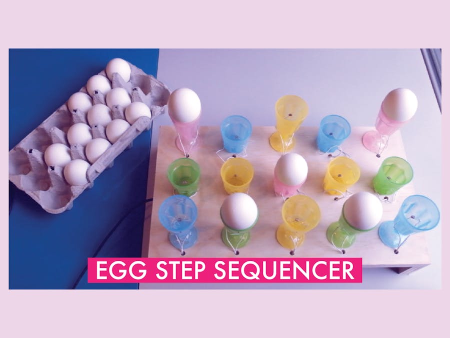
Egg Step Sequencer
The next project I found is still pretty strange and funny, but definitely more directly-related to audio and music! This is the egg step-sequencer project created by Patt Vira:
The video above provides an overview of how Patt created the project, and also includes a demo of the sequencer in action. The visual component of the project itself is not dissimilar to a typical step sequencer, and is very intuitive to those already familiar with the components of a sequencer. Instead of different lights that indicate the presence of a certain drum or sound on a musical step, however, Patt uses eggs placed in little egg holders. When an egg is present in one of the holders, that means that a particular note will be triggered. From what I can tell, she set the top row to play C, the middle row to play E (the third), and the bottom row to play G (the fifth). Each column roughly represents a different beat. On the inside of each of the egg holders, there are light sensors, or photo resistors, that can detect light or darkness. In this case, this is important because if it is dark, that means the egg is covering the sensor, which in turn will tell the program to play the specific note. She used both Arduino and Max to create this project. In Arduino, I believe that most of the code revolves around the directions the program needs to follow (play this note at this time when the photo-resistor is active etc.), while Max seems to cover the programming of the hardware, which includes assigning a specific variable to darkness for each of the sensors. Overall, I think this is a really cool project, and an interesting way to demonstrate how step-sequencers work.
BlueTooth Self-Playing Organ
This next project takes me back to when I was really little. My family and I used to go to this ice cream parlor in Cape Cod called “The Sundae School” to get ice cream sundaes, and in the middle of the restaurant there was a self-playing piano, where, for a quarter, it would play a selected song. I thought it was really cool (and a little eerie, honestly it would freak me out) at first, but over the years it sort of wore down and went tremendously out-of-tune, and it became just as terrifying as it was interesting to me. It is safe to say that the self-playing piano at Sundae School was not digitally-operated or based on any complex MIDI messages from what I could tell, but I figured I would take this opportunity to take a look at a self-playing organ in hopes of both conquering my fears and learning more about how some of these instruments might work!
This project is created using a Reed Organ, which in this case resembles an upright piano very closely, and the actual mechanics of how this operates are incredibly complex, and expensive! For simplicity, on the mechanical side of things, each key is triggered by a solenoid, which is a type of electromagnet that becomes activated when an electrical current runs through it. These solenoids (there are 95 of them in this project) will pull the keys downward, allowing them to sound. Several Arduino micro-controllers are linked to each of these solenoids, and dictate whether the key is pressed or not based on the song. From what I can tell, there are a lot of mathematical calculations and trial-and-error that goes into deciding which solenoid to use in order to ensure that it has enough strength to force the key downward. After this video, I believe the creator of this project also added a vacuum motor to control the foot pedals. Needless to say, this is a very mechanically intense project, and I have really only covered the most basic ideas that allow this organ to function. On the electronics side, it seems a little more simple. Arduino runs a code that decodes MIDI messages, which will trigger various pins on the Arduino. These pins are again connected to the Solenoids, so they control which keys are played. This data is communicated to via Bluetooth. So, essentially, as long as you have the MIDI data, the piano will play any song you want if you run the data through the program. In my opinion, while it will never make any mistakes, it will definitely never sound as great and expressive as a person.
The last project I looked into is called “The Paper Piano.” The “Paper Piano” is exactly what it sounds like: a piece of paper with keyboard notes drawn on it, that you can play like a piano. Below is a video that shows you the piano, and gives you a sense of how it works.
This project is made up a few main components: a led-drawn visual of a keyboard, capacitive sensors, paper clips to hold the sensors in place, and of course, an Arduino, which allows the keyboard to function. The capacitive touch sensors are set to a specific sensitivity, so that it can detect whether you are touching each respective key or not. There is a sensor for each key, and it appears that the black (sharp/flat) keys are left out. Somehow, according to the creator of this project, these sensors are even able to detect whether your hand is above the key? The Arduino itself performs a different function in this project than I would have initially thought, which is measuring the time it takes for the capacitance formed between your hand and the sensor to “charge,” and then producing the respective pitch of the piano key. I think that the sounds that are outputted are programmed within Arduino, and not from an outside DAW, so the keyboard functions more as a monophonic synthesizer than a MIDI keyboard. I found this project interesting because I had not seen how capacitive touch sensors work, and I also thought the setup seemed remarkably simplistic for such a complex function.
Digital Electronics Final Projects
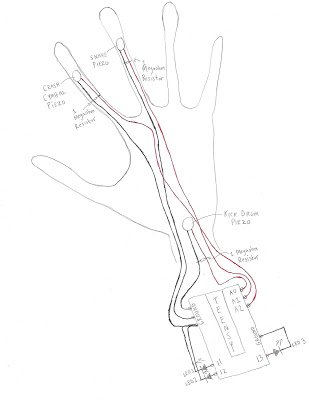
Yasmin Williams: “The Drum Glove”
“The Drum Glove” is a unique MIDI controller, which allows the user to play drum samples using their hands by wearing the special, motion-sensor glove. In Yasmin’s example, she is able to play the guitar with her left hand, and play drum samples with her right hand. In this way, the project adds a level of versatility to multi-instrumental recording and performance experiences. Using sensors on the glove, each of which correspond with an LED, different hand movements trigger varying MIDI messages which are sent from the glove into the DAW, resulting in the sounding of various samples. Arduino code allows these MIDI messages to be sent, and establishes the overall connection between the DAW and the glove. Overall, I thought this was an amazing project and a really cool approach to designing a new MIDI controller.
Here is a sketch of the glove:
Margaret Sohn: Frequency-Based Light Show
Margaret’s project is an amazing visualizer that is triggered by different frequencies from a singer, which results in super interesting, reactive visuals. My favorite part of this project is just how reactive and well-timed the lights are with the vocals, given that the lights completely rely on the vocals. It creates a fantastic connection between the visual and auditory experiences in watching a performance. When the vocalist sings into a microphone, which is connected to a Teensy, the frequencies of the audio signal are interpreted by the electronics, and trigger different lighting effects of various colors. The Arduino coding provides the Teensy with the information needed to recognize these frequencies, and light up the corresponding lights. The result is an amazing light show.
Here is a sketch of the project:
Shane Patterson: “Drum Sequencer”
Shane’s project is a really cool, 16-track 8-32 step drum sequencer. I think the aesthetic aspect of this sequencer is amazing; I love the use of the different colored LED’s on each of the buttons. This drum sequencer is also made with some useful features, including potentiometers that alter the velocity of the notes, a directional pad that allows the user to access all 32 of the steps and alternate between the 16 tracks, buttons that increase and decrease the tempo, and buttons that increase and decrease the project length. Programming in Arduino allows each of the buttons to trigger different MIDI messages, and ultimately create sound in this sequencer. Overall, this drum sequencer is both very functional and aesthetically-interesting.
Here is the drum sequencer in action:
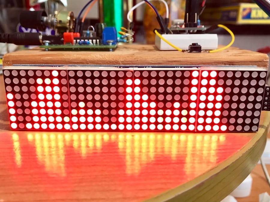
Nick Royall: “MIDI Step Sequencer and Keyboard”
When I initially viewed Nick’s project, I was immediately overwhelmed by the intricacy and literal amount of code, and the complexity of his physical circuit that his project required. Similarly, after watching his video and listening to the SoundCloud demo, I was blown away by the functionality of the project. Nick’s project is essentially a MIDI drum sequencer, keyboard, and synthesizer all together in one circuit. For this post I organized this project into three separate modes: synthesizer mode, keyboard mode, and drum sequencer mode. In synthesizer mode, you can toggle between four different waveforms, generated by Teensy, (sine, sawtooth, triangle, and square), play the notes using buttons, and adjust the pitch via potentiometers that correspond with each button. I think every button is by default tuned to a C Major scale. In keyboard mode, you can play keyboard sounds also generated by Teensy, but I think there is MIDI functionality that would presumably allow you to play a variety of different sounds from different DAW’s. There is also a drum sequencer function. LED lights indicate which step features a note, and the project uses Teensy-generated snare, 808 kick, and hi-hat sounds. In addition, there is a potentiometer that controls the tempo.
Here is a video of the project in action:
Kelly DiCicco: Light Harp
Kelly’s project is so inventive and creative! Essentially, it models the idea of a harp, where playing a string triggers a certain note, except, instead of strings, the project uses beams of light. Instead of strumming strings, you break the stream of light with your hand to play a note. The box is by default tuned to a C Major scale, but flipping a switch on the side of the box changes it to C# Major, so you have access to all of the notes. Additionally, there is a knob on the side that controls volume. Using a combination of code from Arduino and code in Max, the project functions as a sort of light harp, where light sensors detect the stream of light being broken by your hand. There are LEDs for each note on each side of a box, and photocells that will detect whether there is light present or not. The Arduino code controls which note will play depending on which light, and the Max code controls more of the hardware functions. I don’t know anything at all about Max, but I’m assuming it would have to do with the physical sensors. I love this project, here’s a link to it below!
2.) Brainstorm:
An idea that I started thinking about in my research is some creating some kind of digitally-influenced music box. I’m not sure if this is practical or something that anyone would be interested in, but I thought of it as I was researching the self-playing organ. The self-playing piano that I saw was completely analog, and it was somehow connected to a music box scroll that would play additional bell sounds. A rotating metal piece operated by a crank would pluck individual protruding pins, allowing music to sound.
But what if I was able to input some type of MIDI data that would allow a music box to play any song that I wanted, and I could operate the playing of the song with a cute little crank? I can’t tell if that is too ambitious or not ambitious enough, but ever since I read about the self-playing piano, I’ve convinced myself that someone needs to make music boxes way less scary and a little bit cooler. I’m not sure how I would attempt this at all. Maybe the inside would function as a monophonic synthesizer, and I would somehow be able to translate different MIDI messages of each song into code? Maybe instead of a crank or lever, there would be a potentiometer that would control the speed of the song? Still, that wouldn’t completely emulate the function of a music box. And what about melodies that require multiple octaves? Again, I’m not sure how to even begin to approach this, but I think it could be really cool!
Here’s a very rough sketch of how I think it would look and possibly function:
In making changes to this circuit, I decided to start with a simple alteration. I changed the delay time on the green and blue LEDs from 500 milliseconds to 1000 milliseconds, or a full second. This ultimately means that the blue and green LEDs will blink more slowly. I completed this by changing the functions “delay(500)” to “delay(1000).”
Add an additional LED
The second idea I had for altering this circuit was to add an additional LED that would light up with the yellow LED when the button is not pushed. I first added another LED into the simulation, and connected the cathode to ground with black wire, and the anode to the Arduino Uno using white wire, to match the white LED. Next, I turned my attention to coding. I plugged the LED into the fifth pin, so I wrote “int whiteLedPin = 5;” so that the code would recognize it. I then wrote “pinMode(whiteLedPin, OUTPUT);” under setup. From here, I turned off the white LED by writing “digitalWrite(whiteLedPin, LOW);” under “if(digitalRead(buttonPin) = HIGH)”. I wanted it to turn on only when the button was not pressed, along with the yellow LED, so I wrote “digitalWrite(whiteLedPin, HIGH);” under “else”.
Change the pin numbers for the green and blue LED’s
I have no experience with coding at all, so I thought it would be a good idea for me to practice using different pin numbers, and altering them in the code. I moved the green LED to pin number 6 and the blue LED to pin number 7. I then changed the code so that it would correspond with the new pin numbers, by writing “int greenLedPin = 6; int blueLedPin = 7;” instead of “int greenLedPin = 4; int blueLedPin = 5;”. As I adjusted the inputs, I also tried to angle the wire so that it would appear more organized by creating bends in the wire.
Make the green LED and blue LED blink asynchronously
My next idea was to code the blue LED and green LED to blink asynchronously, meaning that they would no longer blink together. To achieve this, I simply changed the blue LED to at first be off (or LOW) before the delay, and then turn on (or HIGH) after the delay. So instead of “digitalWrite(blueLedPin, HIGH);”, it now reads “digitalWrite(blueLedPin, LOW);” before the delay, and reads “digitalWrite(blueLedPin, HIGH);” following the delay.
Add two more LEDs that line up with the blue and green LEDs.
I liked the back-and-forth asynchronous lighting of the LEDs when the button is pushed, so naturally, I decided to add some more LEDs and code them to blink as well! I followed a process identical to the second change by inputting two more LEDs, red and orange, into pins eight and nine, respectively. I decided to choose a pink wire for the red LED, so that it would not appear as though it was going to power. From here, I utilized the same setup process, in establishing the pin numbers, and outputs for the LEDs. Once this was set up, I focused on getting these LEDs to blink. I wanted them to blink together slightly after the green LED, and stop blinking after the blue LED. After adjusting the delay times and arranging the order of each of the functions, I arrived on a result most similar to my initial idea, where the green and blue blink briefly before turning on the red and orange LEDs, respectively. I also ensured that the red and orange were off when the button was not pushed, by setting them to “LOW” under “else.”
Functions I Could Not Figure Out:
I struggled coding some of my other ideas, and I would often receive coding errors when attempting them in the simulation. For example, I had issues with replacing the button with a slide-switch. I initially thought that I could simply delete the button and insert the switch in its place, making nominal alterations to the code. However, after attempting this, flipping the switch did not alter the state of the circuit. I think that this process and the code is likely a little more complicated.
I also struggled with coding the yellow LED to blink. I followed a similar procedure to the one shown in the video, but I often received error messages. I’m not sure if there is a difference between coding this function for “if” or coding for “else,” but I could not quite get it to work. As I said previously, I have no experience with coding, so it is entirely possible that I am missing something very simple. Overall, I had fun trying out some different ideas!
“The Drum Glove” is a unique MIDI controller, which allows the user to play drum samples using their hands by wearing the special, motion-sensor glove. In Yasmin’s example, she is able to play the guitar with her left hand, and play drum samples with her right hand. In this way, the project adds a level of versatility to multi-instrumental recording and performance experiences. Using sensors on the glove, each of which correspond with an LED, different hand movements trigger different MIDI messages which are sent from the glove into the DAW, resulting in the sounding of various samples. Arduino code allows these MIDI messages to be sent, and establishes the overall connection between the DAW and the glove. Overall, I thought this was an amazing project and a really cool approach to designing a new MIDI controller.
Here is a sketch of the glove:
Margaret Sohn: Frequency-Based Light Show
Margaret’s project is an amazing visualizer that is triggered by different frequencies from a singer, which results in super interesting, reactive visuals. My favorite part of this project is just how reactive and well-timed the lights are with the vocals, given that the lights completely rely on the vocals. It creates a fantastic connection between the visual and auditory experiences in watching a performance. When the vocalist sings into a microphone, which is connected to a Teensy, the frequencies of the audio signal are interpreted by the electronics, and trigger different lighting effects of various colors. The Arduino coding provides the Teensy with the information needed to recognize these frequencies, and light up the corresponding lights. The result is an amazing light show.
Here is a sketch of the project:
Shane Patterson: “Drum Sequencer”
Shane’s project is a really cool, 16-track 8-32 step drum sequencer. I think the aesthetic aspect of this sequencer is amazing; I love the use of the different colored LED’s on each of the buttons. This drum sequencer is also made with some useful features, including potentiometers that alter the velocity of the notes, a directional pad that allows the user to access all 32 of the steps and alternate between the 16 tracks, buttons that increase and decrease the tempo, and buttons that increase and decrease the project length. Programming in Arduino allows each of the buttons to trigger different MIDI messages, and ultimately create sound in this sequencer. Overall, this drum sequencer is both very functional and aesthetically-interesting.
After doing some research on Arduino, I found that it has many uses in both the audio world and other realms of electronics. In my research on music and audio, I found an audio-based project called “32-Band Audio Spectrum Visualizer Analyzer.” Essentially, the electronics inside of the analyzer are able to recognize the various frequencies of any signal that is inputted into it. In response to the varying frequencies of the audio signal that are interpreted by the electronics, the signal is visualized by LED’s on the outside of the circuit, which reactively light up. Looking at the LED’s, the user can get a cool and useful visual of the frequency spectrum on a particular audio signal. On the website, the creator of the project provides information on the materials needed, the features, the code they used, the schematic, and any additional instructions needed to create and understand the visualizer.
For this part of the assignment, I wanted to find a really weird, niche project, and I think I succeeded! For Halloween, Matthew Harrell created a giant Lego version of the game Operation, where trick-or-treaters would use a large pair of tweezers to take out candy from a Lego Frankenstein. The thing that stands out the most about project is the enclosures for these circuits, as they are gigantic versions of Lego people: one Frankenstein, and one a mad scientist. On the post, Matthew provides the very in-depth process of creating these giant enclosures from scratch and putting them together. In terms of electronics, like the game operation, Frankenstein and the mad scientist respond when the tweezers hit the boundaries of the different open spaces on Frankenstein. The electronics interpret these hits, and trigger mp3 files to make it sound as if both of the figures are speaking, and also some information that causes them to shake their heads, and move their arms and legs in a pretty scary way. Each opening on Frankenstein causes different audio files and movements to be triggered, which creates some variety in reactions. Regarding Halloween, Matthew notes at the end of his blog post, “Everything works fantastically and held up to a full night of abuse,” and man, I hope he’s kidding!
Here is a video of the electronics testing:
Here is an image of everything mounted:
Here are some images of the finished product (for size reference, look at the pumpkin in the bottom left corner):
Here is a video of Matthew playing the game (watch out, the animatronic movement is pretty scary):
Digital/Analog Inputs
In digital electronics terms a switch or button is a digital input, an LED is a digital output, and a potentiometer is an analog input.
Computer Programming Experience
I have no computer programming experience, so this is all new to me! 🙂
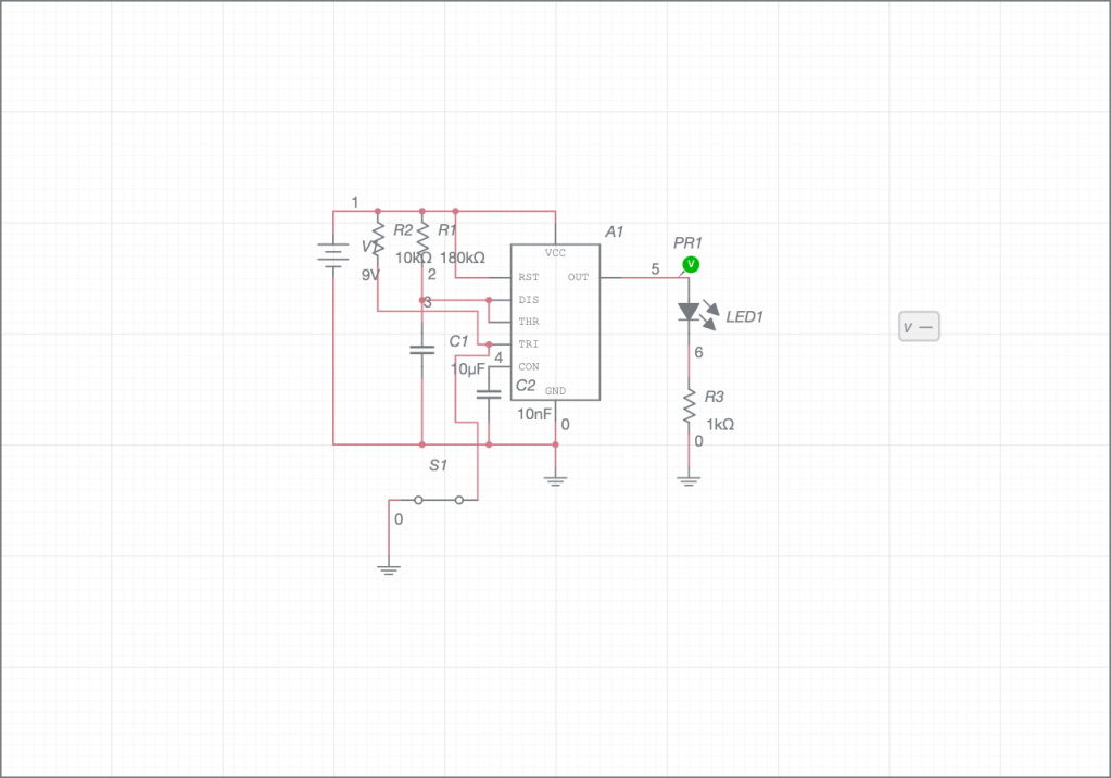
t= 2 seconds C= 10 uF (0.00001 F) R1= ? t= 1.1 x R x C 2 seconds= 1.1 X R X 0.00001F 2 seconds= R X 0.00011 181818.18 Ohms= R1
At first I tried to use a 200k Ohm resistor in this circuit, to get a high of about 2 seconds, but this was not super precise, so instead I used a 180k Ohm resistor.
Here is a screenshot of the circuit working with the oscilloscope (I tried my best!), but I couldn’t really alter the voltage/div:
Additional Uses for the 555 Timer: Bike Turning Signals
Looking at the additional uses for the 555 Timer, I decided to look at a bike turning signal. The schematic looks like this:
A turning signal is of course used to indicate to other vehicles and pedestrians whether the biker is turning left or right, so two of these circuits are required on either side of the bike to allow the person to signal both of these directions. This circuit is an astable multivibrator, because the light blinks consistently on and off for a certain amount of time that is established by the values of R1 and the capacitor. It is very important for safety reasons that this is astable because when using it, the biker needs to be able to indicate which direction they are moving in for an indefinite amount of time, with the blinker consistently turning on and off, until they make the turn. When they make the turn, there should be away to turn the signal off (or if it were a car turn signal, it often automatically turns off after making the turn) so that the light stops blinking, until they need it to make another turn. Overall, these 555 Timers have a wide variety of important uses.