Monostable Multivibrator
First, let’s solve for R1.
t= 2 seconds
C= 10 uF (0.00001 F)
R1= ?
t= 1.1 x R x C
2 seconds= 1.1 X R X 0.00001F
2 seconds= R X 0.00011
181818.18 Ohms= R1
At first I tried to use a 200k Ohm resistor in this circuit, to get a high of about 2 seconds, but this was not super precise, so instead I used a 180k Ohm resistor.
Here is the link to my Multisim Circuit:
Multisim Live: Analog Lab Week 12
Here is an image of the schematic:
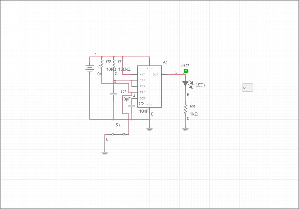
Here is a screenshot of the circuit working with the oscilloscope (I tried my best!), but I couldn’t really alter the voltage/div:

Additional Uses for the 555 Timer: Bike Turning Signals
Looking at the additional uses for the 555 Timer, I decided to look at a bike turning signal. The schematic looks like this:
A turning signal is of course used to indicate to other vehicles and pedestrians whether the biker is turning left or right, so two of these circuits are required on either side of the bike to allow the person to signal both of these directions. This circuit is an astable multivibrator, because the light blinks consistently on and off for a certain amount of time that is established by the values of R1 and the capacitor. It is very important for safety reasons that this is astable because when using it, the biker needs to be able to indicate which direction they are moving in for an indefinite amount of time, with the blinker consistently turning on and off, until they make the turn. When they make the turn, there should be away to turn the signal off (or if it were a car turn signal, it often automatically turns off after making the turn) so that the light stops blinking, until they need it to make another turn. Overall, these 555 Timers have a wide variety of important uses.
