Analog Electronics Lab #11

Guitar Pedal Research

Pedal Manufacturers:
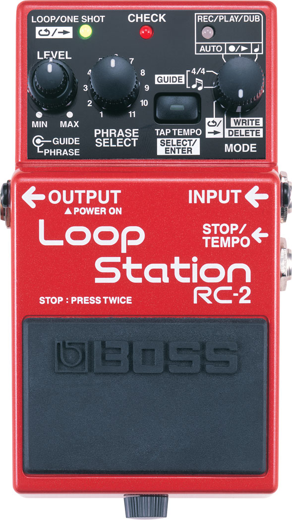
BOSS Pedals

I personally own the RC-2 loop pedal, which I love! I love using it because it offers me the ability to overdub and add percussion to my guitar playing, if I don’t have a friend to play with. Musically, I love working in layers to try out different ideas, so the loop pedal is a perfect way to practice and perform different arrangements. BOSS makes many different variations of the loop pedal, and seems to be the most popular manufacturer for this particular type of pedal, and for most different types of guitar pedals. They make loop pedals, distortion pedals, pitch modulation pedals, reverb pedals, synth pedals, among many others. Their website claims that their “stompboxes,” meaning their famous single pedals, are the top-selling in the world. I love the look of their pedals, and their reliability. However, I would guess that because BOSS pedals are made in such mass quantities, that they are not handmade, and they likely aim for total consistency across their pedals, so they all sound the same. In this way, it could be difficult to achieve a truly unique sound from a large manufacturer. Given that it is such a large company, it might also be difficult to have the same level of customer specialization (custom guitar pedals) and service that a smaller boutique would have, giving the relationships that they can form directly with their customers.

SY-1

Fulltone Pedals

Fulltone Pedals seem to specialize in overdrive distortion pedals, such as the OCD V2 and the Soulbender V2. Given their name, “Fulltone,” they specialize in tone pedals, rather than loop pedals and pitch modulation. While their products don’t have a very wide variety of functions, they do have competitive pricing and seem to have spent a lot of time perfecting the tone of their pedals. Additionally, unlike large manufacturers, they have a custom shop, where they sell new variations on their existing pedals in limited quantities. These items seem to rotate constantly, so that they always have new, different approaches to tone alteration. On the product descriptions for the custom items, the owner often writes a personal note about how he stumbled across certain parts and decided to try to make something new. He is often very specific about the actual electronics of the pedals, unlike some of the larger manufacturers that focus on the effects. From the about page, the owner, Michael Fuller, says he is focused on durability, and recreating the tone of vintage guitar pedals with consistency, longevity, and the best possible tone in mind (at the bottom of the page it says: “Specifications and features of Fulltone pedals are subject to change depending on what sounds best to my ears.“)

70-BC Fuzz - Cosmetic Blem
OCD V2 - Cosmetic Blem

Effectivity Wonder Pedals

Effectivity Wonder Pedals is a small guitar-pedal manufacturing company based out of Barcelona, Spain. The unique look of these pedals immediately struck me, and I looked through their website to learn more. They create a wide variety of different types of pedals at a competitive price, including FX pedals, distortion pedals, and synthesizer pedals. All of their products are handmade. Many of their pedals seemed to be named and designed with different celebrities and characters in mind, including the “Winona Driver” distortion pedal and the “GhostBoosters” FX pedals. I love these unique designs. I also really like the idea of creating custom guitar pedals. They have executed some really cool, custom designs, and encourage customers to choose crazy images and tone effects to make something brand new. This customization is a feature that many other guitar pedal manufacturers and distributors do not offer. However, I wish I had more of sense of what these pedals are going to actually sound like when looking online. They do not have any demonstration videos on their website, and they do not say what is going on with the electronics of their pedals.

raul_600x600

Differences in Approach:

In examining these different manufacturers, it seems like larger manufactures are focused on variety, consistency, and information resulting effects of their pedals, rather than the actual electronics. In this way, their products are very accessible, in that their customers don’t have to understand anything about electronics to be able to understand their products’ functions. However, their prices are very high in comparison to some of the smaller boutiques, and they do not provide the same level customization options, and personalization, which makes all of their pedals very standardized, and can make achieving something truly unique more difficult. Conversely, smaller boutiques offer lower prices, more customization, and generally more information regarding electronics. This can be really helpful for someone who knows exactly what they’re looking for and has a good understanding of electronics, but someone is maybe a little less experienced and looking for many different options would likely choose a larger manufacturer as a starting point. Overall, both of these types of approaches have their drawbacks and advantages, making a choice really depends on your budget and your understanding of what you’re looking for!

Unique Guitar Pedal:

One crazy guitar pedal I found is the Catalinbread CSIDMAN Glitch/Stutter Delay. It is essentially a slapback delay pedal with some randomizer that varies the lengths of each delay, and creates an interesting stutter effect.

This video demonstration shows how it works:
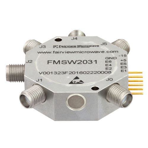
SP5T Switch

An SP5T switch looks like this:

SMA PIN Diode Switch SP5T From 100 MHz to 20 GHz Rated at +27 dBm high resolution

Here is a diagram of how it works:

SP5T-Switch

The name, SP5T, indicates that it is a single-pole, five-throw switch. The switch is a rotary switch, meaning that it is circular and can stop in different positions. In this case, the switch can stop in five different positions.

Momentary Button vs. Latching Button

A momentary button only remains compressed when someone is pushing the button, whereas a latching button is a button that compresses and decompresses with a button push. More simply, a latching button stays compressed with a push, and can be decompressed with another push, while a momentary button is only compressed when someone is pushing it, and when the person releases it, the button is decompressed. A momentary button can be used for playing a note on a synthesizer, as you want the notes to release when someone lets go. Conversely, you might use a latching button for a guitar pedal, to engage the effect, without having to keep pressing it. In this way, the latching button allows for a sustained effect, without having to keep pushing it. To remove the effect, it just has to be pushed again. Overall, latching buttons are the best option for guitar pedals and momentary buttons are the best option for synthesizers.

Analog Electronics Lab #10

Circuit Link:

https://www.multisim.com/content/zaaTfb5fmWVrXXU97BJhTV/analog-lab-10/open/

Completed Circuit:

Extra Credit:

For the extra credit, I decided to add a switch that could alternate between symmetrical and asymmetrical distortion.

https://www.multisim.com/content/Zrbu54En22yBxHoGaH2mHh/analog-lab-10-extra-credit/open/

Analog Electronics Lab #9

1. For the circuit below, if the signal is loud enough to distort, which of these will the output signal look like?

Screen Shot 2020-03-27 at 6.49.41 PM.png

If the signal is loud enough to distort, the output signal will look like answer A, the symmetrical distortion.

Screen Shot 2020-03-27 at 6.42.00 PM.png

2. For the circuit below, if the signal is loud enough to distort, which of these will the output signal look like?

Screen Shot 2020-03-27 at 6.49.10 PM.png

If the signal is loud enough to distort, the output signal will look like answer B, the asymmetrical (single-sided distortion).

Screen Shot 2020-03-27 at 6.41.15 PM.png

3. Is it safe to assume that the output of these two circuits will sound the same and be the same volume?

Screen Shot 2020-03-27 at 7.00.03 PM.png
Screen Shot 2020-03-27 at 7.00.36 PM.png

The output of these two circuits will not sound the same or be of the same volume because the second circuit has a buffer, and the first circuit does not. Without a buffer, the resistance of the speaker/headphones and the resistance of the diodes interact in a strange way, behaving as though they are in parallel, which can result in a significant decrease in volume, or some bizarre distortion effect that we do not want. However, with a buffer, we are able to avoid this through the nature of the feedback loop, which produces a strong output signal without the strange, undesired effects of the diodes’ resistance or a great volume decrease. To achieve this, plug the input signal into the positive input, and plug the output signal into the negative input. From here, it will be possible to properly hear and control the distortion effects. Overall, the distortion effects will sound correct with the buffer like in the second circuit, and the sound will be strange or very quiet without a buffer like in the first circuit.

4. Fill-In-The-Blank Question:

Below is the schematic for the circuit I made in the video. I’d refer to the potentiometer at the end, right before the output circuit, as the “crossfader.” With this circuit, if you turn the crossfader all the way to one side you’ll hear a completely clean signal.  If you turn the crossfader all the way to the other side you’ll hear the signal at its maximum level of distortion.

5. If you turn the potentiometer to its halfway point, you’ll hear…

If you turn the potentiometer to its halfway point, you’ll hear a blend between the distorted signal and the clean signal. So, the signal is not completely clean, but it’s not at its maximum level of distortion either, it is at a balanced blend between the two. You’ll hear the exact average of the voltages of the two signals.

Analog Electronics #8

Questions:

1) With the oscillator we’re studying the comparator outputs a square wave and the integrator outputs a triangle wave.

2) With an integrator, if Vin is positive the output voltage ramps down (up/down). If Vin is negative the output voltage ramps up (up/down).

3) With a comparator, if the op amp’s + input is connected to a greater voltage that that connected to it’s – input, the op amp’s output will be about positive (positive/negative) 9v DC.  If the op amp’s + input is connected to a lower voltage that that connected to it’s – input, the op amp’s output will be about negative (positive/negative) 9v DC.

4) There’s a formula for how fast the integrator ramps up or down: change in volts per second at Vout = -Vin / RC

So the bigger the resistance R you use the slower the ramp gets, and the bigger the capacitor gets the slower the ramp gets.

5) The circuit at the end of this video is a monophonic synthesizer – it can only output one tone at a time. What do you think would have to do to make a polyphonic synthesizer that could play 2 notes at the same time? 3 notes? 4 notes? 100 notes?

Unlike a monophonic synthesizer, which only allows the user to play one note at a time, a polyphonic synthesizer offers more variety by allowing for multiple notes to be played at a time. In order to create a polyphonic synthesizer, instead of having one master potentiometer that connects separately to each of the push buttons and potentiometers, we would get rid of the master potentiometer, and connect each of the notes separately and directly into the comparator. In the monophonic synthesizer, the voltage flows into a master potentiometer which divides into three different signals. However, directly connecting the voltage coming from the comparator into each of the notes would allow more than one to be played at the same time. For example, in order to play 2 notes at the same time, we would connect two buttons and potentiometers directly into the comparator, for 3 notes, we would connect three buttons and potentiometers directly into the comparator, and for 100 notes, we would connect one hundred buttons and potentiometers directly into the voltage, while using the necessary resistors. Theoretically, given that we have enough parts and space, we could create as many notes as we want, and play as many as we want of them at the same time. Overall, removing the master potentiometer and having each push button and potentiometer separately connected to the comparator with their own resistors will allow us to create a polyphonic synthesizer.

Analog Electronics Lab #6

Low-Pass Filter:

Potentiometer Value: 10,000 Ohms
Corner Frequency= 1/(2pi X R X C)
20 Hz.= 1/(2pi X  10,0000 Ohms X C) X (C/1)
(1/20 Hz.) X 20 Hz. X C= 1/(2pi X 10,000 Ohms) X (1/20 Hz.)
C= 1/(2pi X 10,000 Ohms X 20 Hz.)
C= 1/(1256637.06144)
C= 0.00000079577 Farads
C= 0.79577 uF

From here, I rounded up and decided to use a 1 uF capacitor.

Photo of Circuit:

High-Pass Filter:

Potentiometer Value: 100,000 Ohms
Corner Frequency= 1/(2pi X R X C)
20,000 Hz.= 1/(2pi X 10 Ohms X C)
20,000 Hz. X C = 1/(2pi X  10 Ohms X C) X (C/1)
(1/20,000 Hz.) X 20,000 Hz. X C= 1/(2pi X 10 Ohms) X (1/20,000 Hz.)
C= 1/(2pi X 10 Ohms X 20,000 Hz.)
C= 1/(1256637.06144)
C= 7.95774715e-7 Farads
C= 0.000000795774715 Farads
C= 0.795774715 uF

From here, I rounded up and decided to use a 0.1 uF capacitor

Photo of Circuit:

Schematic:

Answer This Question:

I think that you create a 12dB/octave filter by doubling the value of the cutoff frequency in the equation, and solving for the values of resistance and capacitance that you need to create this filter. Since we are making a -6dB filter using the cutoff frequency, I think it would make sense to double this frequency in order to create a -12dB filter. For the -18dB filter or -24dB/octave filter, I would triple or quadruple this value of the cutoff frequency, respectively. This would yield increasing amounts of resistance values for the potentiometer or capacitor, which would allow us to achieve these effects (?)

Final Project:

  1. Describe in a few sentences a Final Project you think you could build, which would be interesting to you, which appears to be at about the skill level of the analog students from last year. 

    I would be interested in trying to guitar pedal with distortion, low pass or high pass filters or other effects. I saw that a few people completed this project in previous years, and I thought their project came out really cool, and I liked the amount of control they had over the tone of the guitar. I really love to play the guitar, and I think working on building a guitar pedal would be a cool way to learn more about the way they work and how effect pedals work.
  2. Describe in a few sentences something you could build which you think might be slightly more difficult than that, but maybe possible, which would make a compelling Final Project for you. 

    I do not have good judgement on what would be a difficult project and what wouldn’t be, but I would also be interested in making a square wave synthesizer, with each note tuned to one of the notes of the pentatonic scale, that would make improvising easier than a regular major or minor scale. Additionally, making each key trigger a chord in a major or minor key would be really cool, but I think it might be too ambitious. Overall, though, I think tuning each note to the pentatonic scale would be a cool and (maybe) different take on the synthesizer project.
  3. Describe in a few sentences any type of professional, sold-in-stores analog audio electronics which you find compelling and wish you could understand, design, and build. 

    I am really intrigued by experimental guitar pedals with strange effects. Beyond just regular distortion pedals or loop pedals, there are also pedals dedicated to providing the guitar with really unusual sounds, like synthesizer sounds, emulate a simple square wave or more complex synth. I’ve even seen a pedal intended to imitate the sound of a flock of birds. I’ve always wanted to know and understand the electronics of the pedal, and how they are able to produce these weird effects using a complex combination of familiar effects. Also, I’ve never tried one of these guitar pedals, so it would be interesting for me to make my own unique pedal, and be able to use it.

Troubleshooting Log:

Click here to check it out!

Analog Electronics Lab #5

DC Blocking, Current Limiting Circuit

Why is adding a resistor and a capacitor on the inputs and outputs of your circuit a good idea?

Adding a capacitor and resistor on the inputs and outputs of the circuit can help to block dangerous DC voltage from inadvertently damaging sensitive headphone or headphone jacks. Overall, adding them is a good safety precaution.

Non-Inverting Amplifier

Short Video:

Calculations:

Vout= Vin X (1+ R2/R1)
0.2V= 0.1V X (1 + R2/10K Ohms)
2= (1+ R2/10K Ohms)
1= R2/10k Ohms
R2= 10K Ohms

Non-Inverting Amplifier with Potentiometer:

Video:

Calculations:
Gain = Vin * (1 + R2/R1)
0.2V= 0.1V X (1 + R2/10K Ohms)
2= (1+R2/10K)
1= R2/10K
R2= 10K Ohms

Gain = Vin * (1 + R2/R1)
0.1V= 0.1V X (1+ R2/10K Ohms)
1= (1 + R2/10K Ohms)
0= R2/10K Ohms
R2= 0 Ohms

Inverting Amplifier:

How is the inverting amplifier different from the non-inverting amplifier?

As we can see from comparing the two videos, in a non-inverting amplifier, the input and output signals are both perfectly aligned and in-phase. However, in an inverting amplifier, the input and output are both clearly out of phase. After some research, I found that in an inverting amplifier, the input and output signals are 180 degrees out of phase with each other.

Short Video:

Calculations:
Gain = -Vin*(Rf/Rin) 
0.2V= 0.1V X (Rf/10k Ohms)2= Rf/10k Ohms
20k Ohms= Rf

Troubleshooting Log:

Made some mistakes this week. Check them out here!

Analog Electronics Lab #4

Oscilloscope Videos:

Controls Photo:

Controls of the Oscilloscope Explanation:

Power: The power button, which varies in location on each oscilloscope but is generally fairly obvious, turns the oscilloscope on and off.

Input Mode: The input mode controls what type of signal is visible on the screen of the oscilloscope. A ground signal will show just a straight line, since it is set to show zero (ground level), and DC will show the actual signal, since it is set to project the signal. Always set the oscilloscope to DC when attempting to see the signal, as AC will show something confusing in our situation.

View Mode: The view mode shows which signal is present on the screen of the oscilloscope. The CH.1 mode will show the signal from channel 1, the CH.2 mode will show the signal from channel 2, the DUAL mode will show both of them at the same time, and the ADD mode will show the two signals summed together.

Vertical Position Knobs: The vertical position knobs move each signal from channel 1 and channel 2 up and down on the grid. Set it to 12 o’clock in our case to properly see the signal. Other knobs, like the Intensity, Focus and Horizontal Position knobs, can also help to make the signal(s) appear clearly on the screen.

Volts Per Div Knobs: The small knob on the volts per div control should always be turned all the way to the right until it clicks. The larger knob on the volts per div control controls the vertical display and is measured in volts per division. Each division represents one of the squares made by the vertical and horizontal lines. Adjusting this will control how “tall” the wave appears on the screen. However, it is important to note that we are only adjusting how the wave appears on the screen, not altering the amplitude or any other property of the signal in changing the appearance. In our case, setting it to 0.5V will provide the clearest picture.

Time Per Div Knobs: The time per div knobs control horizontal display, and is measured in time per division. Adjusting this will control how “long” or “short” the wave appears by zooming in and out on the wave, by adjusting how much time each division shows. It is important to note that we are only adjusting how zoomed in the signal appears, not altering the actual wavelength or frequency of the signal. We can use this knob to alter how many complete waves the display will show. In our case, we want to see 2-4 full waves, and setting it to around 0.5mS/div will help us achieve this.

Trigger Controls: 
Most simply, the trigger controls just tell the oscilloscope at which point in the signal to begin drawing the waveform based on a certain voltage. We can think of them as controls as providing the voltage a selected signal must meet in order for the oscilloscope to begin drawing the signal(s) from the channel(s).

Trigger Level: The trigger level sets the voltage level at which the oscilloscope will begin drawing. In our case, keeping it right at 12 o’clock will give us a clear view of our signal.

Trigger Source: The trigger source determines which signal must be at the certain voltage set by the trigger level in order for the oscilloscope to begin drawing. In our case, we will set this to Channel 1. It is important to note that just because we are setting this to Channel 1, we will still be able to view the signals from both Channel 1 and Channel 2. The trigger source is completely independent from View Mode; trigger source is just selecting the signal that must meet a certain voltage in order for the oscilloscope to begin drawing the signal(s).

Trigger Mode: The trigger mode determines when the oscilloscope will draw the signal, based on different requirements that are determined by the given mode setting. In our case, we can set the trigger mode to either AUTO or TV-V

Trigger Position: The trigger position knob essentially holds the wave in place, by properly aligning it horizontally and subsequently timing it correctly. In our case, set the knob right in the middle to align it for observation.

Volts Per Div. vs. Time Per Div.

The oscilloscope seeks to show the difference in voltage overtime. Time is on the X-axis, and voltage is on the Y-axis. “Volts per div” controls the vertical display, in that adjusting it will change the amount of volts visible in each division on the oscilloscope, and subsequently change how the wave is presented vertically. Lowering the number of volts per division will make the wave appear “taller,” in that not as many volts can fit into each division. Conversely, raising the number of volts per division will make the wave appear “shorter” (in terms of the vertical) or smaller, in that each division can hold more volts. “Time per div” controls the horizontal display, and adjusting it will change how much time is in each division, resulting in alterations in how the wave appears horizontally. Increasing the time per div will allow the user to see more cycles of the waveform, as they are allowing each division to show how the wave moves over a greater time per division. Alternatively, decreasing the time per div will allow the user to see less cycles of the waveform, as they are allowing each division to show how the wave moves over less time per division. Adjusting these controls will allow the user to find the clearest, most sensical way for them to view the wave. However, it is important to note that we are only adjusting the visual parameters of the signal, and we are not changing characteristics of the actual waveform.

Trigger Controls Explanation

The “trigger” controls in the most basic sense all contribute to telling the oscilloscope at which point in the signal to begin drawing the waveform by setting a certain voltage that a certain signal must meet in order for the oscilloscope to draw. This primarily involves four different controls: trigger level, trigger source, trigger mode, and trigger position. Trigger level controls the level of voltage required for the selected signal to meet to allow the oscilloscope to draw. Setting it right in the middle is a good idea for our situation. Trigger source determines which signal must meet this voltage. In our case, we want this to be the input or channel one signal, so we would set the trigger source to CH.1. The trigger mode decides when the oscilloscope will draw the waveform, based on different requirements determined by each mode. For this lab, it is most appropriate to use AUTO or TV-V mode. Finally, the trigger position allows the user to hold the wave in the proper place. In our situation, setting the knob in the middle will allow us to view it properly.

Connecting the Breadboard to the Oscilloscope

To connect the breadboard to the oscilloscope, first, insert two black probes on the ground rail of the breadboard. It is important that these are on the ground rail, as there is no power running through the circuit! For the first channel, clip the black clip to one of probes, and clip the red clip to the green wire on the outside of the potentiometer that is directly connected to the resistor. For the second channel, clip the black clip to the remaining probe, and clip the red clip to the other green wire that is connected to the middle of the potentiometer.

Potentiometers with Input and Output

As I turn the potentiometer, I am increasing the level on the output signal by gradually decreasing the amount of resistance on the output signal. When it is turned all the way to the left, the resistance is maximized and the amplitude is minimized, and subsequently it just appears as a straight line on the oscilloscope. As I turn it to the right, I am decreasing this resistance, and as a result, and the signal’s amplitude increases on the oscilloscope. When it is turned all the way to the right, there is no resistance, and the signal can be seen (and heard if plugged into a speaker) at its full amplitude (or volume). In this case, the potentiometer is really just a volume knob. The minimum amplitude of the output wave as a percentage of the input wave is 0% when there is maximum resistance and the potentiometer is turned all the way to the left, and the maximum amplitude of the output wave as a percentage of the input wave is 100% when there is no resistance and the potentiometer is turned all the way to the right. The maximum can only be 100% because it would be impossible for the output to be at a greater volume or amplitude than the input, as there is no amplifier.

Troubleshooting Notes

Made a few mistakes this week. Check them out here!

Additional Resources

I found some of the controls a little confusing this week, especially the trigger controls, so I used some additional resources to figure out the answers to these questions.

https://core-electronics.com.au/tutorials/oscilloscope-triggers-what-how.html

https://learn.sparkfun.com/tutorials/how-to-use-an-oscilloscope/all

Analog Electronics Lab #3

Soldering

When you first walk up to the soldering iron….

When I first walk up to the soldering iron, I should first moisten the sponge used to clean the soldering iron, and make sure all of the equipment needed to solder (materials that are being soldered, and a device to hold up these materials if necessary) is present. Following this, I can open up a window. This will allow some of the harmful, unpleasant fumes from the melting solder to escape the room. Once the window is open and I have gathered all the materials I need, I can ensure that the soldering iron is plugged in and turned on, and set the temperature between around 4 and 5. After a few minutes, the soldering iron should heat up. Before I actually begin soldering, however, it is important to clean and prepare the soldering iron. To accomplish this, I should melt some of the solder on the tip of the iron to burn off some of the old solder residue, and then wipe off this residue on the sponge. I will know that the iron is prepared properly when the tip appears shiny and clean. Once all of this is prepared properly, I can begin soldering. 

When you step away from the soldering iron…

Before stepping away from the soldering iron, I should first prepare the iron for the next person by melting solder on the tip of the iron to take off some of the residue, and then cleaning off this residue on the sponge. This makes the preparation process significantly easier for the next person. While they will likely have to clean it again before beginning to solder, it prevents any excessive residue buildup. As a critical safety precaution, it is extremely important to turn off the soldering iron. If you don’t, you could burn down NYU! (might be a little dramatic, but seriously, it’s dangerous)

Current and Power

Setting the Multimeter:

Before starting to use the multimeter, be sure to check that the red test lead is plugged into the red jack on the bottom of left of the multimeter that is labeled “A” for amps. Since current is measured in amps, it is easy to remember that in order to measure current, the red test lead must be plugged into the jack labeled “A.”

Power Through A Resistor:

Calculated:
P=VI
V=8.90V
P= 0.25W
I= ?
0.25W= 8.90V X I
0.25W/ 8.90V= I
0.02808988764 Amps = I

V= 8.90V
I= 0.02808988764 Amps
R= ?
V= IR
8.90V= 0.02808988764 Amps X R
8.90V / 0.02808988764 Amps = R
316.84 Ohms= R

Since the calculated resistance is 316.94 given this voltage and current, the smallest resistor I can use is 330 Ohms.

Measured:
To check my calculations, I set up the circuit with my 8.90V battery and a 330 Ohm resistor, and measured the current.

Measured Current= 0.027 Amps

Since 0.027 Amps is very close to 0.02808988764 Amps, I know that both my calculations and my math are correct.

Kirchoff’s Current Law:

Measured:
I1= 0.026
I2= 0.009
I3= 0.009
I4= 0.003
I5=0.005
I6= 0.024

Calculated:
I1= I2 + I3 + I4 + I5= I6

I1 and I6:
Voltage= 9.68 V
Resistance=
R= 1/ ((1/R1) + (1/R2) + (1/R3)+ (1/R4)).
R= 1/ (1/1000) + (1/1000) + 1/(2200) + 1/(3300)
R= 1/ (0.001) + (0.001) + (0.00045454545) + (0.0003030303)
R= 1/ 0.0027575753
R= 362.637422811 Ohms

Current=
V= IR
9.68V= I X 362.637422811
0.02669 Amps = I1 and I6

I2 and I3:
R= 1000 Ohms
V= 9.68V
V=IR
9.68V= I X 1000 Ohms
9.68V/1000= I
0.00968 Amps= I
0.00968 Amps= I2 and I3

I4:
R= 2200 Ohms
V= 9.68V
V=IR
9.68V= I X 2200 Ohms
9.68V/2200 Ohms= I
0.0044 Amps= I
0.0044 Amps = I4

I5:
R= 3300 Ohms
V= 9.68V
9.68V= I X 3300 Ohms
9.68V/3300 Ohms= 0.002933 Amps
0.002933 Amps= I
0.002933 Amps= I5

Troubleshooting Notes:

You live and you learn. Check out my mistakes from this week here!

Analog Electronics Lab #2

Section 1: Resistance

Here are my three resistors and their measurements!

  1. )Color code:  red, red, orange, gold
    Stated resistance value: 22k
    Tolerance: + or – 5%
    Min/max possible resistance: /
    5% of 22k ohms = 1.1k Ohms
    minimum= 20.9k Ohms
    maximum= 23.1k Ohms
    Actual measured resistance: 21.88k
  2. )Color code: yellow, purple, orange, gold
    Stated resistance value: 47k
    Tolerance: + or – 5%
    Min/max possible resistance:
    5% of 47k= 2.35k Ohms
    minimum= 44.65k Ohms
    maximum= 49.35k Ohms
    Actual measured resistance: 46.49k
  3. )Color Code: brown, black, yellow, gold
    Stated resistance value: 100k
    Tolerance: + or – 5%
    Min/max possible resistance:
    5% of 100k ohms= 5k Ohms
    minimum: 95k Ohms
    maximum: 100k Ohms
    Actual measured resistance: 99.2k Ohms

Section 2: Resistors in Series

Values of Resistors Individually (Stated Values):

  1. 22k Ohms Resistor (actual measured value= 21.88k ohms)
  2. 47k Ohms Resistor (actual measured value= 46.49k ohms)
  3. 100k Ohms Resistor (actual measured value= 99.2k ohms)

Values of Resistors Collectively:

Calculated Collective Value: 169k ohms (using actual measured values 167.57k)
Using Stated Values:
22k Ohms + 47k Ohms + 100k Ohms= 169k Ohms
Using Actual Measured Values:
21.88k Ohms + 46.49k Ohms + 99.2k Ohms= 167.57k Ohms

Actual Measured Collective Value: 167.4k Ohms

Schematic:

Section 3: Resistors in Parallel

Values of Resistors Individually (Stated Values)

  1. 22k Ohms Resistor (actual measured value= 21.88k Ohms)
  2. 47k Ohms Resistor (actual measured value= 46.49k Ohms)
  3. 100k Ohms Resistor (actual measured value= 99.2k Ohms)

Schematic:

Total Resistance of the Circuit Using Measured Values (Calculated): 

Using Measured Values:
1 / [(1/R1) + (1/R2) + (1/R3)]
R1:  21.88k Ohms
R2: 46.49k Ohms
R3: 99.2k Ohms

=1/ ([1/21.88) + (1/46.49) + (1/99.2k)]
=1/ (0.04570 + 0.02151 + 0.01008)
=1/ (0.07729)
=12.93817k Ohms

Using Stated Values:
1 / [(1/R1) + (1/R2) + (1/R3)]
R1: 22k Ohms
R2: 47k Ohms
R3: 100k Ohms

=1/[(1/22) + (1/47) + (1/100)]
=1/[(0.04545) + (0.02128) + (0.01)]
= 1/(0.07673)
= 13.03272

Total Resistance of the Circuit (Measured):

Total Resistance of the Circuit (Measured)= 12.85 Ohms

Section 4: Voltage Dividers

Schematic:

Calculated Vout:
VIN= 9.28V
R1= 46.33k Ohms
R2= 99.0k Ohms

VOUT= VIN X R2/ (r1 +R2)
VOUT= 9.28V X 99.0k Ohms/(46.33k Ohms + 99.0k Ohms)
VOUT= 9.28V X 99.0k Ohms/(145.33k Ohms)
VOUT= 9.28 V X 0.6812k Ohms
VOUT= 6.3216 V

Measured Vout:
(I need to redo this measurement!)
Measured Vout= 1.682 V

Section 5: Resistors in Series and Parallel

Values of the Resistors:

  1. 21.96K Ohms
  2. 99.0K Ohms
  3. 46.29K Ohms
  4. 46.71k Ohms
  5. 21.54k Ohms
  6. 99.5K Ohms

Calculated:
RN = 1/ [(1/R1) + (1/R2)…(1/RN)]
=1/ [1/21.96k Ohms) + (1/99k Ohms) + (1/46.29k Ohms)]
=1/ (0.04553 + 0.010101 + 0.0216094)
= 1/ 0.07723394
= 12.9476756k Ohms

RN = 1/ [(1/R1) + (1/R2)…(1/RN)]
=1/[(1/46.71k Ohms) + (1/21.54K Ohms)]
=1/ (0.02150869 + 0.04642526)
=1/0.06793395
=14.7201804k Ohms

R6 (resistor in series) = 99.5K Ohms

12.9476756k Ohms + 14.7201804k Ohms + 99.5K Ohms
= 127.167856k Ohms

Measured:
=127.5 Ohms

Schematic:

Section 6: Complicated Resistor Networks in Voltage Dividers

Schematic:


Calculated:
V1:
R1= [1 / ((1/R1) + (1/R2)+ (1/R3)]
R1= [1/ (1/21.96k) + (1/99.0k) + (1/46.29k)]
R1= 1/(0.4553 + 0.0101 + 0.02160)
R1= 1/0.487
R1= 2.053388k Ohms

R2= [1 / ((1/R1) + (1/R2)] + 99.5k Ohms
R2= [1/(1/46.71k) + (1/21.54k)] + 99.5k Ohms
R2= 1/[(0.0214) + (0.0464)] + (99.5)
R2= 1/0.0678
R2= 14.7493k + 99.5k
R2= 114.2493 Ohms

VOUT= VIN X R2/ (r1 +R2)
VOUT= 9.28V X 114.2493k Ohms/ (2.053388k Ohms + 114.2493k Ohms)
VOUT= 9.28V X 114.2493k Ohms/ ( 116.297Ohms)
VOUT= 9.28V X 0.98234476576
VOUT= 9.1166V
V1= 9.116


V2:
R1= [1 / ((1/R1) + (1/R2)+ (1/R3)]
R1= [1/ (1/21.96k) + (1/99.0k) + (1/46.29k)]
R1= 1/(0.4553 + 0.0101 + 0.02160)
R1= 1/0.487
R1= 2.053388k Ohms

R1= [1 / ((1/R1) + (1/R2)] + 99.5k Ohms
R1= [1/(1/46.71k) + (1/21.54k)] + 99.5k Ohms
R1= 1/[(0.0214) + (0.0464)] + (99.5)
R1= 1/0.0678
R1= 14.7493k 

R1= 16.80288k Ohms

R2= 99.5k Ohms

VOUT= VIN X R2/ (r1 +R2)
VOUT= 9.28V X 99.5k ohms/ (16.80288k ohms + 99.5k Ohms)
VOUT= 9.28V X 99.5k Ohms/ (116.30288)
VOUT= 9.28V X 0.8555
VOUT= 7.9393
V2= 7.9393V

Measured:
Voltage at Resistor 3: 7.26V
Voltage at Resistor 5: 6.32V

Something is definitely off here!

Section 7: Kirchoff’s Voltage Law

Schematic:

Calculated:
V1:
8.06153V
V1= VIN X  R2/(R1+R2)
V1= 9.28V X 145.29k ohms/(21.96k Ohms + 145.29k ohms)
V1= 9.28V X 0.86870
V1= 8.06153V

V2:
2.56 V
Vout= Vin X R2/ (r1 +R2)
Vout= 9.28V X 46.29k Ohms/(120.96k Ohms + 46.29k Ohms)
Vout= 9.28V X 46.29k Ohms/(167.25k Ohms)
Vout= 9.28V X 0.2767713
Vout= 2.56843767 V

V3: (???)
V3= VIN X R2/(R1+R2)
V3= 9.28V X 120.96/(46.29k Ohms + 120.96K ohms)
V3= 9.28V X 120.96/ (167.25 Ohms)
V3= 9.28V X 0.7232
V3= 6.71156V

(I really don’t know what’s happening here)

Measured:
V1: 5.4735V
V2: 2.56V
V3: 1.216V

Analog Troubleshooting Notes Week #2:

Made so many mistakes this week. Click here to check them out!

Analog Circuit Troubleshooting Notes:

Week #1:

  • One of my biggest issues this week was figuring out how to effectively use the photocell. Instead of ordering the connections resistor, to photocell to LED, I connected the resistor to the LED, and the photocell separately connected to the LED without passing through the resistor. The charge from the battery that flows through the circuit takes the path of least resistance, so in order to make the photocell work correctly, it has to be on this path of least resistance, which involves directly connecting the resistor to the photocell. If it is separately connected to the LED the charge will not flow to the photocell, because it is on a path of higher resistance than the path through the resistor. In short, always remember the path of least resistance!
  • Always remember to finish connecting the LED to ground!
  • When reading schematics, pay attention to what’s connected to the center, and be sure to replicate this in the actual circuit.
  • Make sure to have a clear path from the power to the resistor to the LED. Without a resistor, the LED will burn out!

Week #2:

  • Make sure that the multimeter is set to the right setting, especially when attempting to measure both Ohms and Volts in one session.
  • When using the multimeter to measure voltage, connect the black test lead to ground using a black probe on the ground rail, that way, it will be able to measure the difference between 0V (ground) and the voltage of the point measured.
  • When measuring a resistor, be sure that it is not connected to itself (both legs are in the same row), otherwise it will yield a value of zero, which can provide misleading information.
  • Be sure to complete calculations as you’re measuring, that way you can check both your calculations and your measurements at the same time!
  • Always properly define V2 and V1 to avoid any confusion with the Vout formula.
  • Use the correct formulas for defining resistors in parallel and resistors in series.
  • Honestly, I’m not too sure why some of my calculations and measurements don’t match, and I hope to find out more over the next few classes!

Week #3:

  • Don’t be afraid of using a good amount of solder in trying to solder two things together!
  • Be careful to calculate the correct amount of resistance required for your battery, otherwise you will short circuit your battery and drain it!
  • Make sure to use the multimeter as the “wire” in measuring current.
  • Make sure you set the multimeter to the appropriate measurement: voltage, resistance, current etc. and be aware of what setting the multimeter is at when working.
  • It’s easy to check current measurements by adding them up to see if they equal the total current! Checking them with calculations is also useful.
  • Be mindful of the fact that your battery may not be exactly 9V! Measure to before to ensure accuracy in the calculations.

Week #4:

  • Make sure you set the input modes to DC, not ground, if you want to see them!
  • I burnt myself on the soldering iron! Nothing too devastating, just hurts my pride. Be careful!
  • When soldering the battery snaps, make sure you strip enough wire from the snap and the wire you are attaching, as this will make it easier to hook together.

Week #5:

  • Be careful when reading schematics! There’s only one right answer.
  • Take a video of the oscilloscope to see both channel 1 and channel 2, instead of a picture.
  • Pay close attention to the labels on the Op Amp; they will tell you where to plug everything in!
  • Use the correct equations for inverting and non-inverting amplifiers.

Week #6:

  • Be careful not to plug the potentiometer into ground directly! Use a black wire!
  • You can make the circuit look a lot cleaner and clearer by moving the leg of the potentiometer that you’re not using.
  • Be mindful of the amount of wires you’re using to connect the various components of the circuit. Some of them might be unnecessary!
  • Instead of guessing and checking the amount of capacitance that you need, some simple algebra can go a long way! (Low Pass: plug in highest frequency (20,000 Hz.), and lowest resistance value; High Pass: plug in lowest frequency (20 Hz.) and highest resistance value)
  • Make sure you’re plugged into the the right part of the audio jack, otherwise, you won’t get any sound!
Design a site like this with WordPress.com
Get started